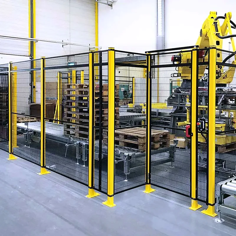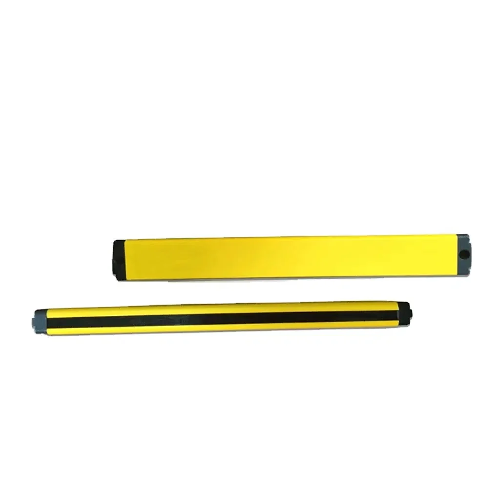
Safety distance and reach distance are not the same.
Two related questions are often confused. First, can a person reach the hazard through, under or over a physical guard? Second, if a person crosses a light curtain or scanner field, can the hazardous movement stop before the person reaches it? Physical dimensions and openings are considered using reach-prevention principles such as ISO 13857. Positioning of electro-sensitive protective equipment and other safeguards uses the approach and response-time methodology in ISO 13855:2024.
How a separation-distance calculation works.
The familiar relationship is often summarised as S = K × T + C: separation distance equals an assumed approach speed multiplied by the total response and stopping time, plus an additional distance that accounts for intrusion or the characteristics of the selected safeguard. The applicable 2024 method contains device- and approach-specific requirements, so the correct variables cannot be selected from a generic online calculator alone.
- S — separation distance: the required position of the detection zone or safeguard relative to the hazard.
- K — approach speed: selected for the defined direction and type of human approach.
- T — total time: from protective-device actuation until the hazardous function achieves the intended risk reduction.
- C or device-specific allowance: accounts for possible intrusion, detection capability and the selected arrangement.
What belongs in total stopping time?
Total time is not simply the braking figure shown on a robot datasheet. The safety chain can include the scanner or light-curtain response, safety relay or PLC logic, communications, robot controller response, connected machine response, drive stopping and mechanical movement. Tolerances, ageing, load, speed and the worst credible operating condition may also matter.
Where the value is not adequately established, stop-time measurement or another justified validation method may be required. The test point, operating condition, sample method, tolerances and result must represent the safety function that the protective device actually initiates.
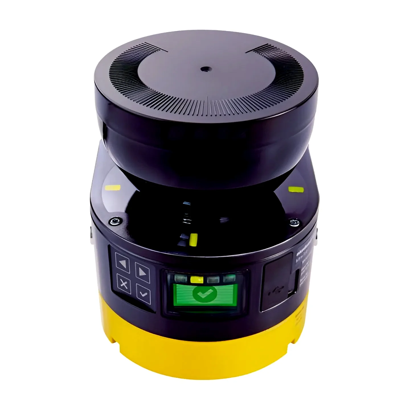
Fencing still needs a safe position.
A fixed guard does not depend on stopping time in the same way as a presence-sensing device, but its position is still safety-critical. Consider the largest robot, tool, payload and workpiece envelope; stopping overshoot; reaching through mesh; reaching over or under panels; climbing; openings for conveyors or pallets; and the possibility of parts, swarf or process material leaving the cell.
Common layout mistakes.
- Using the robot manufacturer's maximum reach as the only boundary.
- Ignoring the length and orientation of the end effector, workpiece or rejected part.
- Positioning a reset control where the complete safeguarded area cannot be checked.
- Allowing a scanner field to be shadowed by pallets, bins, columns or machinery.
- Calculating from a controller value without including the full safety-chain response.
- Changing speed, payload, software or device settings without reviewing the distance.
Apply current editions to the real project.
ISO 13855:2024 is the current international edition for positioning and dimensioning safeguards with respect to human approach. ISO 13857:2019 addresses reach-prevention distances, while ISO 10218-2:2025 addresses integrated industrial robot applications and cells. The applicable British adoption, designated-standard status and project responsibilities should be confirmed at the time of design. See the full robot-cell standards and UK compliance guide.